

Sign up for the Design News Daily newsletter.
Theremin? Bleh! Therebone? Yeah! (Part 4)
One step closer to the soon-to-be-legendary therebone.
Clive 'Max' Maxfield
November 30, 2023
6 Min Read
CLIVE "MAX" MAXFIELD
At the start of this ever-growing mega-mini-series, I explained how it came to pass that I’m currently writing a series of Arduino Bootcamp columns for the electronics and computing hobbyist magazine, Practical Electronics, in the UK.
Now, it must be acknowledged that there is currently a cornucopia of training materials (books, videos, kits) available for people who wish to learn about microcontrollers in general and Arduino in particular, so you may ask, “Does the world really need one more Arduino course?” Well, I must admit to being a tad biased, but I would be obliged to answer in the affirmative. There are many ways to explain things, and I like to think I bring something new to the party, not least my illustrious illustrations, which I painstakingly capture using Microsoft Visio.
A lot of the training I’ve seen spends an inordinate amount of time working with individual light-emitting diodes (LEDs). I wanted to do things a little differently, so we quickly progressed to using the Arduino to drive a single digit common cathode 7-segment display.

Using the Arduino to drive a single digit common cathode 7-segment display. CLIVE "MAX" MAXFIELD
Well, a lot of Poohsticks have passed under the bridge since that humble beginning. First, we learned how to control the segments on the display to represent the decimal digits 0 through 9. Then we added the hexadecimal characters A through F. Also, we discussed how to use the display to present messages like “HELLO” and “Error.”
Next, we added a couple of momentary breadboard-mounted pushbutton switches and used them to cause our display to count up and down. As part of this, we experienced (and conquered) the delights of switch bounce. When we last met in Part 3, we’d just added a piezoelectric buzzer and used it to generate bigger and better “click” sounds whenever we press one of our switches.
So, what would you do if you had a couple of pushbutton switches, a piezo electric buzzer, and a 7-segment display? In the same way that software developers always start with a “Hello World” program, hardware developers in possession of a 7-segment display almost invariably implement a dice-rolling algorithm.
My first pass was simple: press a button and receive a random number between 1 and 6. Meh! Next, we generated a series of random numbers (each accompanied by a piezo-electric click) before settling on a final value. Still meh-ish. What I wanted to do was generate a series of random values that start off quickly, and then gradually slow down until… they… eventually… land… on a final value.
But what transition rate delays should I use? Most of my embedded systems friends said they would start with a best guess set of values and then tweak them. I’m made of sterner stuff. If something can be over-engineered, then I’m the man for the job. First, I practiced clapping my hands to get an audible feel for the visual effect I wished to achieve. Next, I powered-up the Camtasia application I use to record myself when I’m creating a webinar, and I recorded myself clapping with the slow-down rate I required. Finally, I used the cursor to read off the time values, which I used to populate a delay array in my program.

Screenshot of Camtasia recording of me clapping my hands. CLIVE "MAX" MAXFIELD
To be honest, the final effect was rather cool. So, how could I over-engineer it some more? What I decided to do was add a vibration detector to my breadboard. The idea is that—a bit like tilting a pinball machine—once the final value of the dice was being displayed, slapping the table would cause it to generate a different random value.
Initially I was thinking of creating a DIY vibration switch using a spring and a bit of wire, but then I discovered fast (easy to trigger), medium, and slow (hard to trigger) units on Adafruit. Not knowing which to choose, I ordered all three to play with.

Testing vibration switches. CLIVE "MAX" MAXFIELD
I hooked these up to my trusty oscilloscope and observed some very satisfying bouncy waveforms. Eventually, I selected the easy-to-trigger device for this application, so I added it to my main breadboard.
My next experiment involved adding a 10-kΩ breadboard mounted trimpot. Since the Arduino Uno has a 10-bit analog-to-digital converter (ADC), this means analog inputs are translated into integers in the range 0 to 1023. I mapped these integer values into a new range of 0 to 9 and displayed these values on the 7-segment display.
I also used these 0 to 9 values to select between 10 frequencies: C4 (262 Hz), D4 (294 Hz), E4 (330 Hz), F4 (349 Hz), G4 (392 Hz), A4 (440 Hz), B4 (494 Hz), C5 (523 Hz), D5 (587 Hz), and E5 (659 Hz). From whence did I locate these values? I’m glad you asked. There’s a super useful book called Exploring Arduino, Second Edition, by Jeremy Blum. If you visit the page for Chapter 6 on Jeremy’s website and click on the “Download Code” button, you’ll receive a compressed ZIP file containing all sorts of stuff, including a file called pitches.h that contains everything you need on the musical note frequency front.
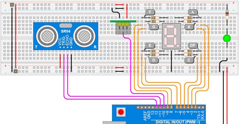
All of which brings us to our current state of play. There’s a super-duper little ultrasonic sensor called the HC-SR04. You can get a compatible device from Adafruit for only $3.95, which is a bargain. When triggered by the Arduino, this little scamp transmits a burst of ultrasonic pulses and measures the time it takes for them to return. It presents the result as a pulse, whose width is equal to the round-trip time.

Using the HC-SR04 to measure distance. CLIVE "MAX" MAXFIELD
The formula to calculate the distance is based on the speed of sound in air. Of course, this is based on a particular value of ambient temperature. How could we over-engineer this? Well, the speed of sound in air is modified by both temperature and humidity, so we could add temperature and humidity sensors to our breadboard and… you get the idea. For the moment, I’ve only just added the HC-SR04 to my breadboard, bending its pins so it points up.

Adding the HC-SR04 to the breadboard. CLIVE "MAX" MAXFIELD
Now I’m ready to commence experimenting. I’ll start by displaying the distance rounded to the nearest centimeter on the 7-segment display (I’ll restrict myself to displaying values from 00 to 99 in pairs: first digit, short pause on, second digit 2, short pause on, long pause off, do it all again).
Next, I’ll use the distance rounded to the nearest centimeter to play notes in the classical scale. But what I’m really looking forward to is using the distance in mm to sound a corresponding frequency, thereby implementing my therebone incarnation of a theremin.
I will, of course, report further in the future. Until then, as always, I welcome your comments, questions, and suggestions.
About the Author(s)
You May Also Like
Editors' Choice

.jpg?width=300&auto=webp&quality=80&disable=upscale)


Jun 4 - Jun 6, 2024
Jun 4 - Jun 6, 2024
Innovation in automation starts here. Discover and collaborate on automation solutions that are revolutionizing the entire production lifecycle — from design to production to market — and sharpen your competitive edge. ATX South is part of IME South, a six-in-one expo offering the latest insights & solutions spanning medtech, packaging, automation, plastics, design, & processing.
Register Now