Meet the Arduino Uno R4 Minima and WiFi, Part 2
How does the performance of the new 32-bit R4s compare to that of the 8-bit R3?
August 2, 2023
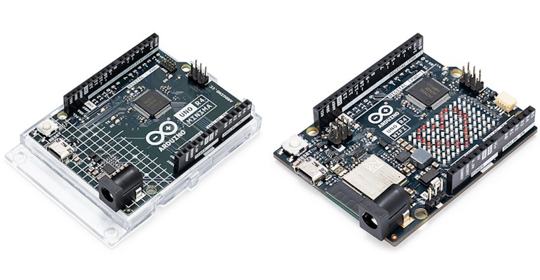
As we discussed in my previous column, until a few weeks ago, the Arduino Uno microcontroller development board we’ve all grown to know and love was the R3 (“Revision 3”). This little rascal is powered by an ATmega328P microcontroller unit (MCU), which proffers an 8-bit data bus, a 16-MHz clock, 2 KB of SRAM (in which to store local variables and any data generated by the user’s program), and 32 KB of flash memory (in which the user’s program is stored). When this board is powered up, it immediately runs whatever program resides in the MCU’s flash memory.
Also of note is the fact that this board’s digital input/outputs (I/Os) switch between 0 V and 5 V, as compared with most of the newer Arduino offerings, which switch between 0 V and 3.3 V. This is important because—due to the open-source nature of the Arduino—a vast ecosystem of plug-in boards called “shields” has come into being. These shields, which are equipped with header pins that match the Uno’s footprint, include sensors, displays, motor controllers, relays, Wi-FI, and myriad other things. Not surprisingly, these shields all expect to see the 5 V signals employed by the Uno R3.
As an aside, even though a 16-MHz clock, 2 KB of RAM, and 32 KB of flash memory may not strike you as being overwhelming, I’ve happily used a bunch of Uno R3s to drive a wide variety of projects over the years, such as my Awesome Audio-Reactive Artifact, for example (where the “Awesome” is part of its official moniker).
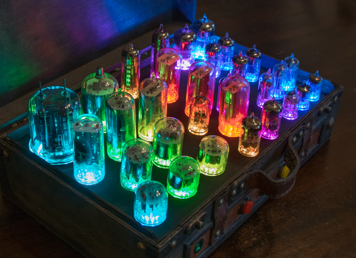
In this case, I started with a small travel suitcase that appears to be an expensive antique crafted out of wood and leather, but that’s really a cheap-and-cheerful imitation intended only for home décor. Next, I took a bunch of broken and discarded vacuum tubes, and I used epoxy to attach these to a thin plywood panel in which I’d drilled holes and painted black.
Next, I attached tricolor light-emitting diodes (LEDs) to the bottoms of the vacuum tubes. These were NeoPixels from Adafruit, which means they can be daisy-chained together. In turn, this means they can all be driven using a single pin on the MCU.
I also mounted a small microphone on the front of the case and used this to feed an 8-pin MSGEQ7 spectrum analyzer device. You can acquire these little scamps as standalone components from SparkFun, or you can purchase pre-constructed breakout boards from SparkFun or on eBay.
The Arduino constantly loops around reading the audio samples and driving the LEDs. When anyone is talking or music is playing, different tubes flicker with different colors to reflect the various frequency components of the sound source. Suffice it to say that this is a real eye-catcher that always attracts attention and positive comments, especially for those of us who were obliged to suffer the minimalistic sound-to-light effects available in the 1970s.
The point of these meandering musings is that my Awesome Audio-Reactive Artifact is powered by an Arduino Uno R3 with lots of “headroom” to spare. However, having said this, I do have projects that require more “oomph” on the processing front. This is why I was so excited when, just a couple of weeks ago as I pen these words, the guys and gals at Arduino released two new versions of the Arduino Uno in the form of the R4 Minima and the R4 WiFi (the folks at Arduino assure me that they have no plans to discontinue the R3 for which they foresee strong continued demand). One very important point is that the R4s provide the same 5 V signals as the R3, thereby allowing us to reuse our existing collection of shields (phew!).
Both R4s are powered by a RA4M1 MCU from Renesas. This little rascal is based on a 32-bit Arm Cortex-M4F core (the ‘F’ means it includes a hardware floating-point unit, which is sadly lacking in the R3). This is, of course, 4X the width of the R3’s 8-bit data bus. The R4’s clock runs at 48 MHz (3X the R3), it’s equipped with 32 KB of SRAM (16X the R3), and it boasts 256 KB of flash memory (8X the R3). The R4 WiFi also boasts an Espressif ESP32-S3 module for WiFi and Bluetooth Low Energy connectivity, but that’s a story for another day.
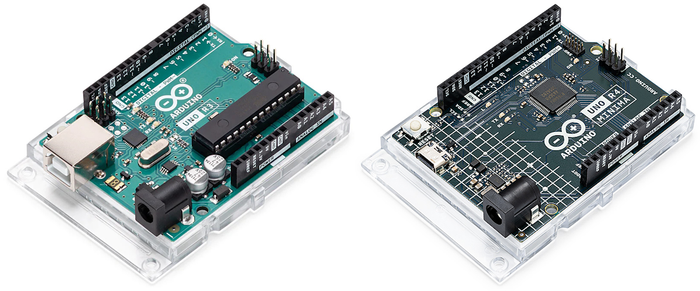
Some of the early PR I saw for the R4s boasted “3X the Performance!” I don’t know about you, but this was a tad underwhelming to me. This number is, of course, derived from the fact that the R4’s 48-MHz clock is 3X the frequency of the R3’s 16-MHz clock, but there’s much more to performance than this. Take floating-point operations, for example. Although the R3’s MCU doesn’t include a floating-point unit (FPU) in hardware, we can still use floating-point operations in our R3 code because the compiler breaks them down into 8-bit “chunks.” Of course, since the R4 MCUs do have hardware FPUs, they should execute floating-point operations much faster.
How much faster? Enquiring minds (like mine) want to know. I’m sure that, if we were to delve deep into the data sheets for these MCUs, we could determine how many clock cycles each operation consumes but (a) who wants to spend time looking through data sheets and (b) where’s the fun in that?
I first determined to explore the relative performance of integer operations. There are three fundamental sizes of integers: short ints, regular ints, and long ints. How big are these data types? It varies depending on the width of the MCU’s data bus and its underlying internal architecture. All the C/C++ specifications have to say about this is that the minimum size of a short int is 16 bits and the minimum size of a long int is 32 bits, while the size of a regular int is anyone’s guess (it’s 16 bits in an R3 and 32 bits in an R4).
As a point of reference, in the case of my integrated development environment (IDE), I’m using the latest-and-greatest Arduino IDE 2. Just to confirm that everything was as expected, I created a simple test program that determines and prints the size of short ints, regular ints, and long ints (the results are presented in terms of 8-bit bytes).
If you wish, you can download a text version of this program to peruse and ponder. I ran this program on both an R3 and an R4. The results are as shown below.

This is, of course, what we expected to see, but it never hurts to check the basic things before plunging into the fray with gusto and abandon (and aplomb, of course).
My ultimate goal is to be able to present a table comparing all of the regular integer operations (+, -, *, /, %, >, etc.) and logical operations (&, |, ^, etc.) on short ints, regular ints, and long ints for both the R3 and R4. I also want to compare floating-point operations (+, -, *, /) on both platforms.
To further this aim, I next created a simple program to evaluate the basic arithmetic operations (+, -, *, /, %) on regular ints. The core of this program is shown below.
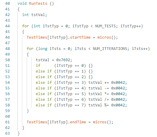
In this case, NUM_TESTS is set to 8 and NUM_ITTERATIONS is set to 10,000,000. What are the first three tests supposed to be doing? Well, I vaguely wondered if an if() test for zero consumed less clock cycles than an if() test for non-zero values, so I decided to check this out. Also, I want to account for the clock cycles used to perform the if() tests so as to be able to isolate them from the clock cycles used to perform the arithmetic operations.
Please feel free to download a text version of this program in the hope you can tell me why if fails to work. “What? It fails to work!” I hear you cry. Yes, I think it’s safe to say that the results, which are shown below, are certainly not what I expected to see.
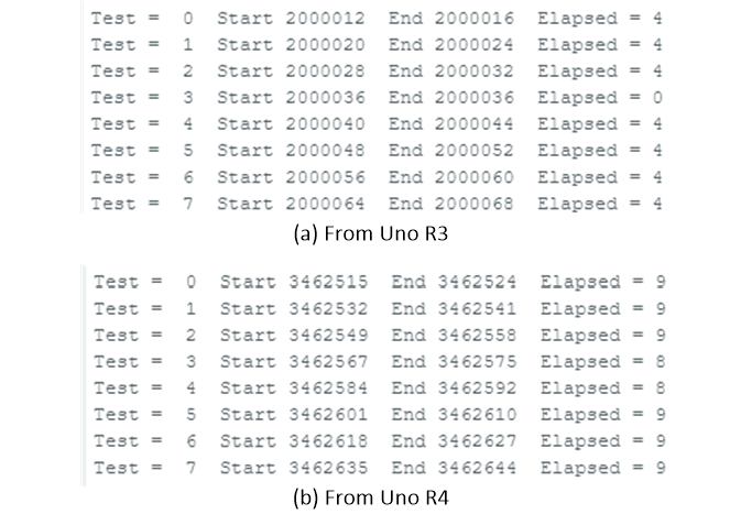
“Oh dear,” I said to myself (or words to that effect). The first thing we observe is that the “Elapsed Time” values for both processors are meaningless (well, obviously they have meaning, but we don’t know what it is). Take just the first if() test on the R3, for example. Assuming this takes 1 clock cycle (and excluding any clock cycles associated with the for() loop), then since we are performing 10,000,000 iterations on an R3 with its 16-MHz clock, we should have an elapsed time of 10,000,000 / 16 = 625,000 microseconds (µs). Instead, we see an elapsed time of only 4 µs.
Whatever is happening here, why is the elapsed time for Test 3 on the R3 0 µs while all the others are 4 µs? And why are the elapsed times for the R4 ~2X those for the R3? And… color me confused.
So, the first high-level question is WTW? (“What the what?”), which became my new favorite expression when my wife (Gina the Gorgeous) and I binge-watched the Happy Shiny People: Duggar Family Secrets documentary on Amazon Prime Video.
The second high-level question is, “Just what is going on here?” I wracked my brains staring at my code trying to spot any obvious “gotchas” to no avail. Next, I instigated a video call with my friend Joe Farr in the UK to ask for his thoughts. It wasn’t long before we unearthed the fundamental issue underlying these pear-shaped results. However, addressing this issue has proved to be another matter entirely. We find ourselves in a battle of wits with an unknown and unseen adversary, and I’ve grown to regret referring to myself as “1/2 Man, 1/2 Beast, and 1/2 Wit.”
All will be revealed in my next column on this topic (by which time I hope to have a solution). In the meantime, I welcome your captivating comments, insightful questions, and sagacious suggestions.
About the Author(s)
You May Also Like


.jpg?width=300&auto=webp&quality=80&disable=upscale)

