Implementing a 1-Digit BCD 8421 Adder, Part 2
Prepare to gasp in astonishment at the cunningness of this solution.
June 14, 2023

In Part 1 of this two-part binary coded decimal (BCD) extravaganza, we introduced a bunch of bodacious concepts, including the binary (base-2) number system, binary logic, binary computers, and bits, followed by the ternary (aka trinary) (base-3) number system, ternary logic, ternary computers, and trits (try saying that sentence ten times quickly).
We also discussed the senary (aka heximal or seximal) (base-6), decimal (aka denary or decanary) (base-10), duodecimal (aka dozenal) (base-12), vigesimal (base-20), and sexagesimal (aka sexagenary) (base-60) number systems.
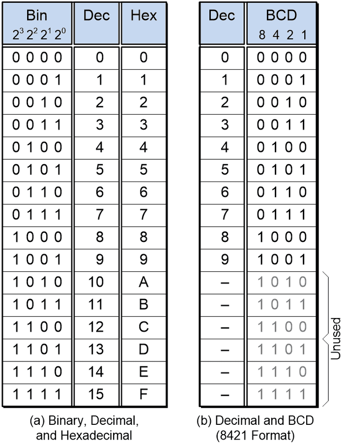
All of this led us to the concepts of the hexadecimal (base-16) number system and binary coded decimal (BCD). There are multiple BCD encoding possibilities, but we started by considering BCD 8421, which may also be referred to as natural BCD (NBCD) or simple BCD (SBCD).

We left Part 1 with a mission, which was to ponder how we might go about creating single digit BCD 8421 adder; that is, a logic function that can accept two BCD 8421 digits, along with a carry-in bit from a previous stage, and then use these values to generate a 4-bit BCD sum along with a carry-out bit to the next stage.

There are several ways in which we might set about doing this. For example, we could do what we do with simpler functions, which is to treat it as a black box, write out the truth table, and then use Karnaugh maps, Boolean algebra, and—possibly—De Morgan’s transformations to decide what combination of primitive logic gates will best serve our purpose.
Like many things, this sounds easy when you say it quickly and loudly, especially if you wave your arms around while doing so, but it’s not so simple in practice. Let’s call our two 4-bit BCD input digits A and B. Each of these can be in one of ten states, which means we have 10 x 10 combinations, which equates to 100 lines in our truth table. But wait, there’s more, because we also have our Cin (“Carry In”) input, which can be 0 or 1, which means our truth table will have 200 lines. Now, I’m not saying that generating the logic for our adder from this truth table cannot be done. What I am saying is that I’m not going to be the one to do it.
Another possibility would be to create a look-up table using some form of non-volatile memory, such as programmable read-only memory (PROM). In this case, we’re going to have nine input (address) bits (two 4-bit BCD digits plus our 1-bit Cin), which equates to 29 = 512 words of memory. On the bright side, this will provide a fast adder function. On the downside, since six of the possible binary combinations remain unused for each BCD digit, we’re going to have a lot of unused (wasted) words in our memory. Even with the words we are using, we require only a 5-bit output (one 4-bit BCD sum plus our 1-bit Cout), but memory devices are typically presented in 8-bit widths, which means we have three unused (wasted) bits in each word.
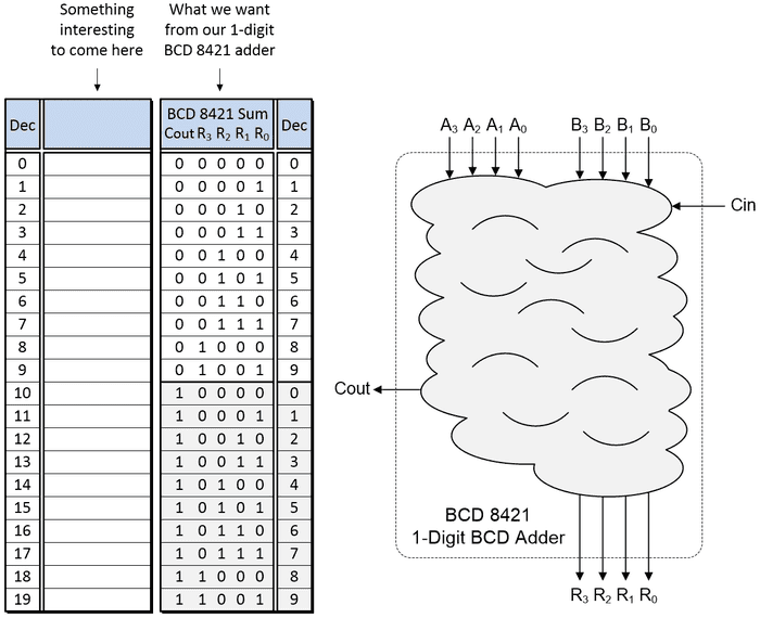
Happily, there’s another way in which we can go about this. Since each of our BCD digits can have a value from 0 to 9, the two extreme cases for our adder are 0 + 0 = 0 and 9 + 9 = 18. If we also consider our Cin bit, which can be 0 or 1, this means we have only 20 different cases to consider, from 0 + 0 + 0 = 0 to 9 + 9 + 1 = 19.
Take a look at the diagram below. On the left, we show a table whose left-hand column represents the decimal equivalent of the 0 to 19 possible cases resulting from us adding two BCD digits (plus carry in). To the right of this table, we show what we want to see coming out of our single digit BCD adder. And on the right of the image as a whole, we depict the logic we need as a “blob.” So, all we need to do now is decide what goes in our “blob.”

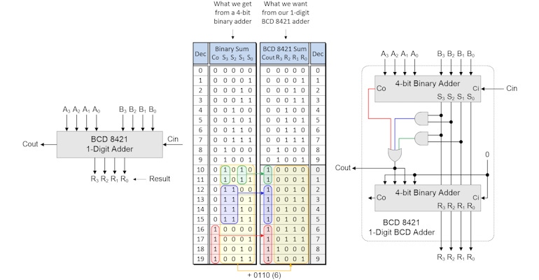
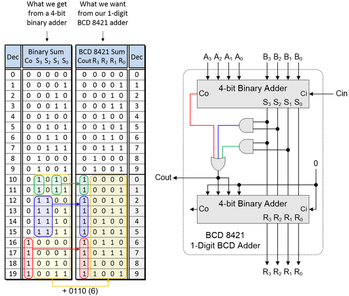
Prepare to gasp in astonishment at the cunning plan we are going to deploy. Indeed, this is a plan so cunning we could pin a tail on it and call it a weasel (as Blackadder would say). What we are going to do is employ a standard 4-bit binary adder. Actually, we are going to use two of these little rascals as shown below.

The table we’ve added shows the results generated by our first (upper) binary adder for the 0 to 19 cases associated with our adding two BCD digits plus the carry in bit. Let’s start by considering the BCD Cout signal in the right-hand table. This is 0 for cases 0 to 9 and 1 for cases 10 to 19.
A clue to the way in which we can generate this signal is provided by the red, blue, and green highlighted areas in the table. What this tells us is that Cout in the right-hand table can be generated as an OR of these highlighted areas in the left-hand table. That is, Cout = Co (red) OR (S3 AND S2) (blue) OR (S3 AND S1) (green). We can see this depicted in our logic gate implementation with the red, blue, and green wires on the right.
Now we turn our attention to the second (lower) binary adder. When Cout is 0, the outputs from this adder (R3, R2, R1, and R0) are identical to the outputs from the first adder (S3, S2, S1, and S0). By comparison, when Cout is 1, the outputs from the lower adder (R3, R2, R1, and R0) (the values highlighted in yellow) are equal to the outputs from the first adder (S3, S2, S1, and S0) plus 6 in decimal (0110 in binary). We can achieve all of this by tying the Ci input to the second adder to 0, also tying bits 0 and 3 of the adder’s second set of inputs to 0, and then connecting bits 1 and 2 of the adder’s second set of inputs to Cout.
I don’t know about you, but I feel a rather rambunctious “Tra-la” is in order. When I was first introduced to this solution, I was blown away by its elegance and (relative) simplicity. Quite apart from anything else, this technique has sparked all sorts of ideas to address other logical conundrums that have come my way. What say you? Do you have any thoughts you’d care to share about anything you’ve seen here?
About the Author(s)
You May Also Like


.jpg?width=300&auto=webp&quality=80&disable=upscale)

